Product Description
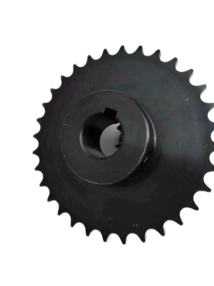
Stainless Steel Plastic Roller Chain Gear Platewheel Engineer Class Agricultural Pintle Cast Iron Weld On Hub Finished Bore Idler Bushing Taper Lock Qd Sprocket
|
European standard sprockets |
|
|
DIN stock bore sprockets & plateheels |
03B-1 04B-1 05B-1-2 06B-1-2-3 081B-1 083B-1/084B-1 085B-1 086B-1 08B-1-2-3 10B-1-2-3 12B-1-2-3 16B-1-2-3 20B-1-2-3 24B-1-2-3 |
|
03A-1 04A-1 05A-1-2 06A-1-2-3 081A-1 083A-1/084A-1 085A-1 086A-1 08A-1-2-3 10A-1-2-3 12A-1-2-3 16A-1-2-3 20A-1-2-3 24A-1-2-3 |
|
|
DIN finished bore sprockets |
06B-1 08B-1 10B-1 12B-1 16B-1 20B-1 |
|
stainless steel sprockets |
06B-1 08B-1 10B-1 12B-1 16B-1 |
|
taper bore sprockets |
3/8″×7/32″ 1/2″×5/16″ 5/8″×3/8″ 3/4″×7/16″ 1″×17.02mm 1 1/4″×3/4″ |
|
cast iron sprockets |
06B-1-2-3 081B-1 083B-1/084B-1 085B-1 086B-1 08B-1-2-3 10B-1-2-3 12B-1-2-3 16B-1-2-3 20B-1-2-3 24B-1-2-3 |
|
platewheels for conveyor chain |
20×16mm 30×17.02mm P50 P75 P100 |
|
table top wheels |
P38.1 |
|
idler sprockets with ball bearing |
8×1/8″ 3/8″×7/32″ 1/2″×1/8″ 1/2″×3/16″ 1/2″×5/16″ 5/8″×3/8″ 5/8″×3/8″ 5/8″×3/8″ 3/4″×7/16″ 3/4″×7/16″ 1″×17.02mm 1 1/4″×3/4″ |
|
double simplex sprockets |
06B-1 08B-1 10B-1 12B-1 16B-1 |
|
American standard sprockets |
|
|
ASA stock bore sprockets |
-2 35-3 -2 40-3 50 50-2-50-3 60 60-2 60-3 80-80-2 80-3 100 100-2 100-3 120 120-2 120-3 140 140-2 160 160-2 180 200 |
|
finished bore sprockets |
|
|
stainless steel sprockets |
60 |
|
double single sprockets&single type Csprockets |
|
|
taper bore sprockets |
35 35-2 -2 50 50-2 60 60-2 80 80-2 |
|
double pitch sprockets |
2040/2042 2050/2052 2060/2062 2080/2082 |
|
sprockets with split taper bushings |
40-2 40-3 50 50-2 50-3 60 60-2 60-3 80 80-2 80-3 100 100-2 120 120-2 |
|
sprockets with QD bushings |
35 35-1 35-2 -2 40-3 50 50-2 50-3 60 60-2 60-3 80 80-2 80-3 100 100-2 100-3 |
|
Japan standard sprockets |
|
|
JIS stock sprockets |
140 160 |
|
finished bore sprockets |
FB25B FB35B FB40B FB50B FB60B FB80B FB100B FB120B |
|
double single sprockets |
40SD 50SD 60SD 80SD 100SD |
|
double pitch sprockets |
|
|
speed-ratio sprockets |
C3B9N C3B10N C4B10N C4B11 C4B12 C5B10N C5B11 C5B12N C6B10N C6B11 C6B12 |
|
idler sprockets |
35BB20H 40BB17H 40BB18H 50BB15H 50BB17H 60BB13H 60BB15H 80BB12H |
|
table top sprockets |
P38.1 |
|
Material available |
Low carbon steel, C45, 20CrMnTi, 42CrMo, 40Cr, stainless steel. Can be adapted regarding customer requirements. |
|
Surface treatment |
Blacking, galvanization, chroming, electrophoresis, color painting, … |
|
Heat treatment |
High frequency quenching heat treatment, hardened teeth, carbonizing, nitride, … |
Customization process
1.Provide documentation:CAD, DWG, DXF, PDF,3D model ,STEP, IGS, PRT
2.Quote:We will give you the best price within 24 hours
3.Place an order:Confirm the cooperation details and CZPT the contract, and provide the labeling service
4.Processing and customization:Short delivery time
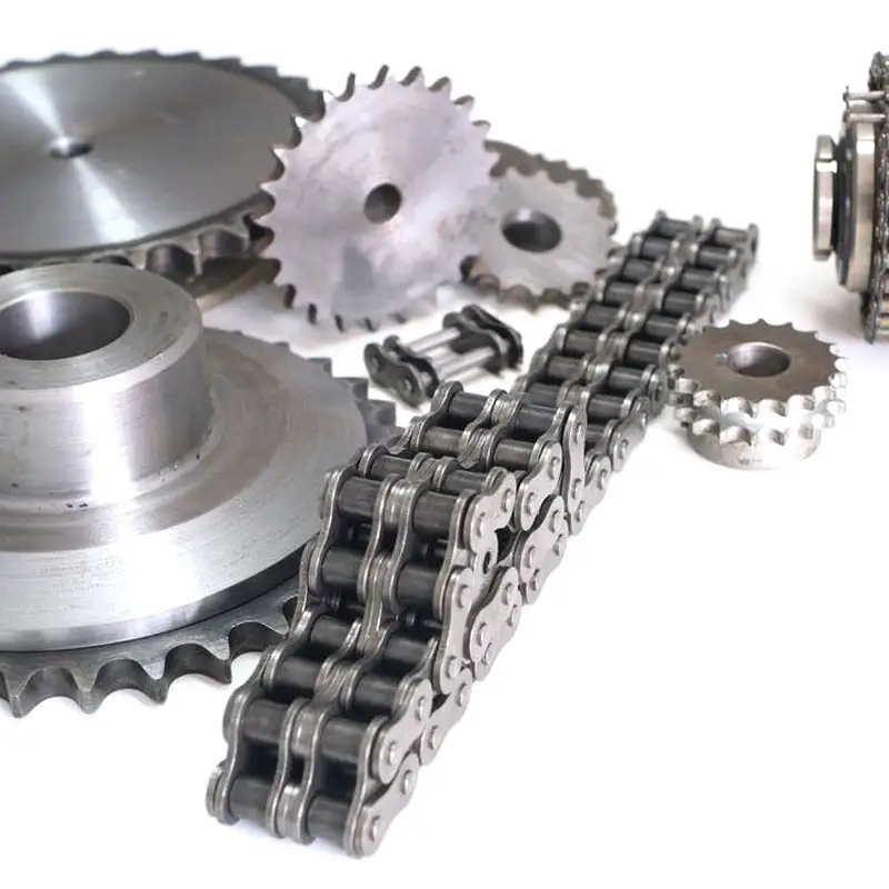
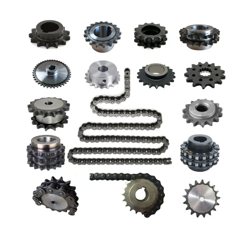
Related products:
Factory:
/* March 10, 2571 17:59:20 */!function(){function s(e,r){var a,o={};try{e&&e.split(“,”).forEach(function(e,t){e&&(a=e.match(/(.*?):(.*)$/))&&1
| Standard Or Nonstandard: | Standard |
|---|---|
| Application: | Motor, Motorcycle, Machinery, Agricultural Machinery, Car |
| Hardness: | Hardened Tooth Surface |
| Manufacturing Method: | Rolling Gear |
| Toothed Portion Shape: | Spur Gear |
| Material: | Stainless Steel |
Calculating Torque Requirements for a wheel sprocket Assembly
Calculating the torque requirements for a wheel sprocket assembly involves considering various factors that contribute to the torque load. The torque requirement is crucial for selecting the appropriate motor or power source to drive the system effectively. Here’s a step-by-step guide:
- 1. Determine the Load Torque: Identify the torque required to overcome the resistance or load in the system. This includes the torque needed to move the load, overcome friction, and accelerate the load if applicable.
- 2. Identify the Sprocket Radius: Measure the radius of the sprocket (distance from the center of the sprocket to the point of contact with the chain or belt).
- 3. Calculate the Tension in the Chain or Belt: If using a chain or belt drive, calculate the tension in the chain or belt. Tension affects the torque required for power transmission.
- 4. Account for Efficiency Losses: Consider the efficiency of the system. Not all the input power will be converted into output power due to friction and other losses. Account for this efficiency in your calculations.
- 5. Use the Torque Equation: The torque (T) can be calculated using the following equation:
T = (Load Torque × Sprocket Radius) ÷ (Efficiency × Tension)
It’s essential to use consistent units of measurement (e.g., Newton meters or foot-pounds) for all values in the equation.
Remember that real-world conditions may vary, and it’s advisable to add a safety factor to your calculated torque requirements to ensure the system can handle unexpected peak loads or variations in operating conditions.
Using a Belt Sprocket in Place of a Chain Sprocket with a Wheel
Yes, in many cases, a belt sprocket can be used in place of a chain sprocket with a wheel, provided that the system is designed to accommodate the change.
Both chain sprockets and belt sprockets serve the same fundamental purpose of transferring rotational motion and power between the wheel and the driven component. However, there are some important considerations to keep in mind when replacing a chain sprocket with a belt sprocket:
- Alignment: Belt sprockets and chain sprockets must be aligned properly with the wheel to ensure smooth and efficient power transmission. Any misalignment can cause premature wear and reduce the system’s overall performance.
- Tension: Chain-driven systems require specific tension to prevent slack and maintain proper engagement between the sprockets and the chain. Belt-driven systems, on the other hand, require appropriate tension to prevent slippage. Ensuring the correct tension for the specific type of sprocket is crucial for reliable operation.
- Load Capacity: Consider the load capacity and torque requirements of the system when selecting a belt sprocket. Belt sprockets may have different load-carrying capabilities compared to chain sprockets, and using the wrong type can lead to premature wear or failure.
- Speed and RPM: Belt-driven systems may have different operating speeds and RPM limits compared to chain-driven systems. Ensure that the selected belt sprocket can handle the desired rotational speed without exceeding its design limitations.
- System Design: Changing from a chain-driven system to a belt-driven system (or vice versa) may require modifications to the overall system design, including the size of the sprockets and the layout of the system. Consult with an engineer or a qualified professional to ensure that the replacement is appropriate and safe.
Overall, replacing a chain sprocket with a belt sprocket can be a viable option in certain applications. However, it’s essential to consider the factors mentioned above and evaluate the compatibility of the new sprocket with the existing system to achieve optimal performance and longevity.
Calculating Gear Ratio for a wheel sprocket Setup
In a wheel sprocket system, the gear ratio represents the relationship between the number of teeth on the sprocket and the number of teeth on the wheel. The gear ratio determines the speed and torque relationship between the two components. To calculate the gear ratio, use the following formula:
Gear Ratio = Number of Teeth on Sprocket ÷ Number of Teeth on Wheel
For example, if the sprocket has 20 teeth and the wheel has 60 teeth, the gear ratio would be:
Gear Ratio = 20 ÷ 60 = 1/3
The gear ratio can also be expressed as a decimal or percentage. In the above example, the gear ratio can be expressed as 0.3333 or 33.33%.
It’s important to note that the gear ratio affects the rotational speed and torque of the wheel sprocket. A gear ratio greater than 1 indicates that the sprocket’s speed is higher than the wheel’s speed, resulting in increased rotational speed and reduced torque at the wheel. Conversely, a gear ratio less than 1 indicates that the sprocket’s speed is lower than the wheel’s speed, resulting in decreased rotational speed and increased torque at the wheel.
The gear ratio is crucial in various applications where precise control of speed and torque is required, such as bicycles, automobiles, and industrial machinery.


editor by CX 2024-02-19