Product Description
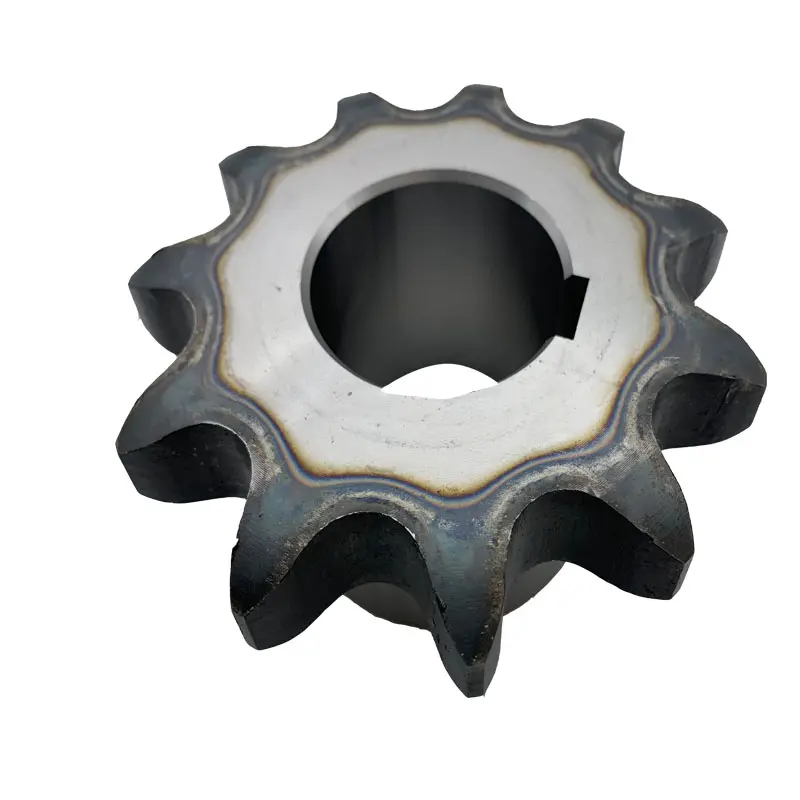
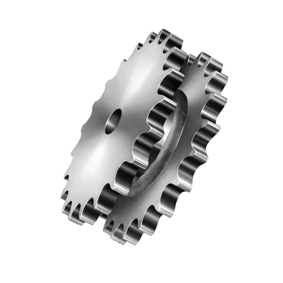
Agricultural Feeder House chain & sprocket For Class Combine
Characteristic
When it comes to maintenance of your class combine, there are many components that are often overlooked. Combine Doctor, a column by Successful Farming magazine, identifies the most neglected parts of the combine. Feeder houses play a critical role in threshing by presenting the CZPT evenly to the rotor or cylinder. One of the components that can be overlooked in preseason inspections is the slats. They should be parallel and not bent or worn. If they are bent or torn, it will cause the feeder house to breakdown.
Upper sprocket is better than lower sprocket
When adjusting the speed of the combine, it is essential to use an upper sprocket rather than a lower one. To do this, the lower sprocket should be removed and replaced by a new one. A good practice is to always run the combine with the feeder house set in the fast position. A large 26-tooth sprocket should be installed on the right side of the feeder house. The sprockets are adjusted in relation to the rotor speed, grain loss monitor, and slugging.
Proper chain tension is critical
To maintain the sprocket, you must have the correct chain tension. To check this, loosen the nuts on the feeder house cylinder lock and turn the adjuster plate clockwise. To make the adjustment, push the cylinder lock handle to “nearly up” position. Remove the multicoupler cover and clean the combine multicoupler face. Loosen the 2 lower pins.
To maintain correct chain tension, you must first adjust the cylinder lock on the header and align the main frame’s top beam with the bottom of the feeder house’s adaptor plate. If this does not produce the desired result, you can tilt the header up and engage the cylinder lock. However, keep in mind that the adjustment might not be sufficient. To avoid losing more than 50% of the sprocket tension, tilt the header slightly.
After adjusting the cylinder lock, back away slowly from the header. Once the combine is fully raised, lower the header and then lift the feeder house saddle. Then, secure the bottom beam lock. If there is a D pin, remove it. Make sure the Stripper Header touches the ground. This is very important. Once you have checked these steps, you are ready to start harvesting.
Avoiding chain jumps off the sprocket
A common mistake that a combine farmer makes is to let the chain stretch when it is being fed. This can lead to the chain getting stretched, and a plug may form in the feeder house. Avoid this by adjusting the chain to fit closely to the auger or draper belt.It is also important to ensure that the chain is not cockeyed. The following are some ways to avoid chain jumps off the feeder house sprocket. at resist wear and tear. Compared to its competition,the HM60 is able to produce a heavier bale than any other model in its class.
Company Information
/* January 22, 2571 19:08:37 */!function(){function s(e,r){var a,o={};try{e&&e.split(“,”).forEach(function(e,t){e&&(a=e.match(/(.*?):(.*)$/))&&1
| Type: | Agricultural |
|---|---|
| Usage: | Agricultural Products Processing, Farmland Infrastructure, Tillage, Harvester, Planting and Fertilization, Grain Threshing, Cleaning and Drying |
| Material: | Iron |
| Power Source: | Electricity |
| Weight: | 5kg |
| After-sales Service: | Installation Guide 3-Year Warranty |
Alternatives to Chain Sprockets in wheel sprocket Configuration
While chain sprockets are commonly used in wheel sprocket configurations, there are alternative methods for power transmission in various applications:
- Gear and Gear Rack: Gears are toothed wheels that mesh with each other to transmit power. Instead of using a chain and sprocket, gears can directly engage with each other, offering a smooth and efficient power transfer. Gear racks, which are linear gears, can be used in place of wheels for linear motion applications.
- Belt and Pulley: Belts and pulleys offer a flexible and quiet means of power transmission. They work similarly to chain and sprocket systems but use belts instead of chains. Pulleys have grooves that grip the belt, allowing power to be transferred between the pulleys.
- Gear Train: A gear train consists of multiple gears meshed together to achieve specific speed and torque ratios. Gear trains are often used in complex machinery and mechanical systems where precise power transmission is required.
- Direct Drive: In some applications, direct drive mechanisms can be used, where the motor or power source is directly connected to the wheel or load without any intermediate components like sprockets or gears.
- Friction Drive: Friction drive systems use the friction between two surfaces to transfer power. One surface, such as a rubber wheel, is pressed against another surface to achieve power transmission.
The choice of alternative power transmission methods depends on various factors, including the application requirements, available space, speed, torque, and efficiency considerations. Each alternative method has its advantages and limitations, and the selection should be based on the specific needs of the mechanical system.
When considering alternatives to chain sprockets, it is essential to analyze the requirements of your application and consult with engineering experts or manufacturers to determine the most suitable method of power transmission for optimal performance and longevity.
Temperature Limits for wheel sprocket System’s Operation
The temperature limits for a wheel sprocket system’s operation depend on the materials used in the construction of the components. Different materials have varying temperature tolerances, and exceeding these limits can lead to reduced performance, premature wear, and even system failure.
Here are some common materials used in wheel sprocket systems and their general temperature limits:
- Steel: Steel sprockets and wheels, which are widely used in many applications, typically have a temperature limit ranging from -40°C to 500°C (-40°F to 932°F). However, the specific temperature range may vary based on the grade of steel and any coatings or treatments applied.
- Stainless Steel: Stainless steel sprockets and wheels offer improved corrosion resistance and can withstand higher temperatures than regular steel. Their temperature limit is typically between -100°C to 600°C (-148°F to 1112°F).
- Plastics: Plastic sprockets and wheels are commonly used in low-load and low-speed applications. The temperature limit for plastic components varies widely depending on the type of plastic used. In general, it can range from -40°C to 150°C (-40°F to 302°F).
- Aluminum: Aluminum sprockets and wheels have a temperature limit of approximately -40°C to 250°C (-40°F to 482°F). They are often used in applications where weight reduction is critical.
It’s essential to consult the manufacturer’s specifications and material data sheets for the specific components used in the wheel sprocket system to determine their temperature limits accurately. Factors such as load, speed, and environmental conditions can also influence the actual temperature tolerance of the system.
When operating a wheel sprocket system near its temperature limits, regular monitoring and maintenance are necessary to ensure the components’ integrity and overall system performance. If the application involves extreme temperatures beyond the typical limits of the materials, specialized high-temperature materials or cooling measures may be required to maintain reliable operation.
How Does a wheel sprocket Assembly Transmit Power?
In a mechanical system, a wheel sprocket assembly is a common method of power transmission, especially when dealing with rotary motion. The process of power transmission through a wheel sprocket assembly involves the following steps:
1. Input Source:
The power transmission process begins with an input source, such as an electric motor, engine, or human effort. This input source provides the necessary rotational force (torque) to drive the system.
2. Wheel Rotation:
When the input source applies rotational force to the wheel, it starts to rotate around its central axis (axle). The wheel’s design and material properties are essential to withstand the applied load and facilitate smooth rotation.
3. Sprocket Engagement:
Connected to the wheel is a sprocket, which is a toothed wheel designed to mesh with a chain. When the wheel rotates, the sprocket’s teeth engage with the links of the chain, creating a positive drive system.
4. Chain Rotation:
As the sprocket engages with the chain, the rotational force is transferred to the chain. The chain’s links transmit this rotational motion along its length.
5. Driven Component:
The other end of the chain is connected to a driven sprocket, which is attached to the component that needs to be powered or driven. This driven component could be another wheel, a conveyor belt, or any other machine part requiring motion.
6. Power Transmission:
As the chain rotates due to the engagement with the sprocket, the driven sprocket also starts to rotate, transferring the rotational force to the driven component. The driven component now receives the power and motion from the input source via the wheel, sprocket, and chain assembly.
7. Output and Operation:
The driven component performs its intended function based on the received power and motion. For example, in a bicycle, the chain and sprocket assembly transmit power from the rider’s pedaling to the rear wheel, propelling the bicycle forward.
Overall, a wheel sprocket assembly is an efficient and reliable method of power transmission, commonly used in various applications, including bicycles, motorcycles, industrial machinery, and conveyor systems.


editor by CX 2024-03-28